Radial
Form tools fall into three groups dependent upon the way in which they are fed into the work, radial, axial and static. We will deal with them in that order.
The radial tool is, as its title suggests fed into the work radially. In its simplest form it consists of a piece of gauge plate filed to shape and subsequently hardened. Points to watch are that there must be both side and front clearance to the cutting edge.
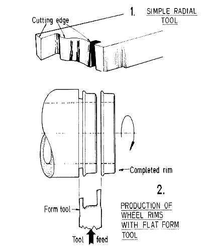
After hardening, the top face should be stoned lightly to produce a sharp cutting edge. Figure 1 shows a typical tool, fig. 2 shows it at work. Tools of this type are most suitable for brass and nickel silver components and will produce several hundred components each before they must be re-made. When an even larger number of components is required or when the material to be cut is such that the tool must be re-sharpened repeatedly then a more elaborate tool must be made.
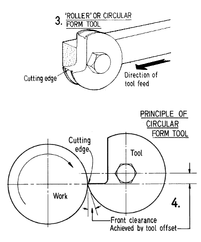
This is the circular form tool which, as its name suggests, is turned up on the lathe. The tool is turned to a reverse profile of the component required and is then hardened and tempered. It is then ground away to produce the cutting edge (see figs 3 and 4). It will be appreciated that the cutting edge may be re-sharpened many times and the tool rotated on its holder to give a very long tool life indeed.
It does have its snags however, and the chief of these is its lack of side clearance, which tends to restrict its use to comparatively shallow cuts. In my own experience the lack of side clearance makes tools with integral parting off tools impractical. In use the tools are mounted in the tool post at centre height and fed directly into the work. If the width of the tool is not too great and the speed not excessive it may be fed in until the appropriate diameter is reached, producing component after component.
Radial forming is a bit like parting off, in that if the tool is not sharp or if the material hangs too far out of the chuck it will chatter. (Alternatively, the digging in and springing out of the tool produces pretty patterns on the surface of the work). If chatter occurs when all the above conditions have been fulfilled, try feeding the tool in a little more resolutely, for chatter often disappears when the loading is increased. It should be realised, however that the owner of the ultra light lathe is not likely to have much success with broad form tools of the radial type.
Axial
Axial tools are very useful if a large number of wheels or something of this sort is required, for they enable quite high production rates to be maintained with high repetition accuracy.
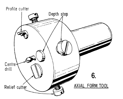
The action of an axial tool is shown in fig. 5 and its construction in fig. 6.
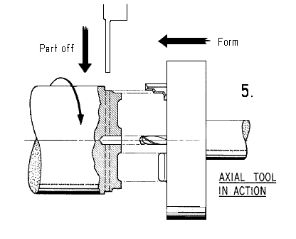
The tool is mounted in the tailstock and, since the cutting edges on one side are balanced by those on the other, very little chatter occurs on even a very light lathe.
The component must still be parted off, although this should be no problem if a very narrow tool is used.
Static
The last type of tool to be described is the static type in which the tool is not fed into the work at all. This is not a misprint, the tool really does work and is ideal for those awkward repetition items which, by virtue of their great length and small diameter, are impossible to turn any other way. One picture is worth a page of prose so have a look at fig.7 which shows the tool. The two top plates are made of gauge plate and are screwed to the body and dowelled to it to ensure that they are replaced accurately during manufacture.
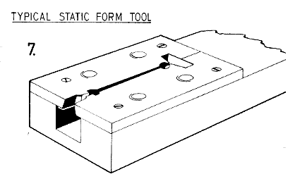
The required shape is then filed out along the joint line, spherical portions being drilled through on the joint and reamed with a tapered broach or tapered reamer from below to give side and front clearance. The top plates are re-assembled to the body and hardened and tempered whilst in position. Finally the top surface is stoned flat to sharpen the cutting edges.
In use the tool is mounted just below centre height underneath the brass or nickel silver wire from which the component is to be made. The lathe is started and the rotating wire pressed down against the cutting edges. The shape is formed on the material slowly until the correct size is obtained, whereupon the component pops through the gap into the body of the tool and cutting ceases automatically. (See fig. 8).
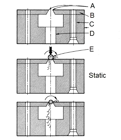
The cutting edges (A) are formed in the hardened top plate (B) which is screwed and doweled to the body (C).
This has cut-outs and clearing holes for the swarf (D).
The material (E) is pressed down onto the cutting edges as it rotates.
Metal is removed until it is the correct size and then passes through between the cutting edges.
This particular tool, while much slower than the others is a most satisfying tool to use!