Colin Binnie explains how the earliest locomotives were built by blacksmith technology
Photographs and drawing © Science and Society Picture Library, The Science Museum, London
Prints availableArchaeology of the locomotive
Originally published in Model Railways, January 1979
A couple of years ago I gave a talk to the `Model Railway Weekend School` at Hassocks on the subject of Early Locomotives
. Since Mike Sharman was to be in the audience and his love for medieval railways is well known, such a talk could well be construed as an attempt to teach Granny Sharman to suck eggs.
The way out of the dilemma was clear. Ignore `Mike`s Medieval Models` and talk on the primeval primitives
. This was a subject dear to my heart anyhow. The talk kept everyone awake and some brave spirits even asked questions afterwards. I was therefore emboldened to develop the theme a little further, this article being the result.
Now it is a curious thing that although `Puffing Billy` is a household word and shares with the `Rocket` the laurels of being the most famous locomotives, there is very little in the way of published engineering data on `Billy`. Of course the `Rocket` was quite a nice locomotive and did manage to win that trial at Rainhill, but it was such a modem engine.
Locomotives had been about for so long by the time of the `Rocket` that they were actually able to run a competition between the products of several locomotive manufacturers. A far cry from the early days of the locomotive. The `Rocket` represents the locomotive in adolescence but `Puffing Billy` and his kin represent the locomotive in early` childhood.
Before we have a look at Puffing Billy let us have a look at the world into which he was born. The year is ‘1813. Last year Napoleon made his disastrous retreat from Moscow and went into exile. The war is over but the economy of agricultural England is not too good. During the war the cost of horse ownership has risen dramatically. The British army has needed horses and horse feed at the expense of the industrial and agricultural user. Despite the first stirrings of the industrial revolution England is still a largely agricultural community, a land of small towns and villages each drawing its sustenance from its immediate locality.

The canal, the last word in high speed transport, is viewed with the same awe that a future generation will give to Concorde and the peak of technical sophistication is undoubtedly the pumping engines of Watt and Trevethick. This is the age of the windmill, the ox drawn plough, Nelson`s `Victory` and the horse.
Looking back it is difficult to really appreciate the difficulties facing the pioneer mechanical engineers in those far off days. Materials and methods which we take for granted today were just not available. Wood was the principal material for the construction of any large machine, metallic components being kept to a minimum. Cost effective design is no new thing, wood was cheap and well understood whilst metal working was expensive and metallurgy largely a matter of custom and common sense.
Iron came in two varieties, cast and wrought. Cast iron could be cast into complex shapes but the quality was to say the least, variable. Cast iron is a material strong in compression but, especially in those days, weak in tension. Specialist iron founders had evolved the cast iron ships gun, notably William Carron who gave his name to the carronade. Note that this application of cast iron was to the shipboard gun where the gun could afford to be massive. The marked preference for bronze by the military artillery man for his lighter pieces was not just for the lovely shine on the barrel!
Wrought iron was at that time produced by the `dry puddling process` whereby the iron was re-melted and de-carbonised by passing air through it to burn off the carbon. Unfortunately it also burnt away half the iron as well, so rendering wrought iron rather expensive. Since this was a manually manipulated process the size of the largest available piece of wrought iron was limited to about fifty pounds in any case.
The lump of iron now had to be hammered or wrought, to remove the slag and to create the fibrous internal structure so characteristic of the material. Wrought iron provided a material which could be hammered out into strip or plate and which could be readily forge welded under the hammer. Unlike cast iron it was comparatively strong in tension along the grain although stressing the material across the grain could cause it to split. Wrought iron behaved like a malleable, tough weldable wood.
Copper and brass were available though expensive; the brass contained more tin than is usual today and was therefore more akin to bronze. Leather and hemp just about completes the list of engineering materials available to the pioneers. The means by which these materials could be shaped were largely confined to the methods of the blacksmith and as we shall see when examining `Puffing Billy`, these methods imposed their own constraints upon the detail design of components.
Most of the hand tools used had a strong affinity to those of the carpenter; saws, the brace and bit, etc. all showed their ancestry. Machine tools were almost non-existent although it was possible to get cylinders bored by specialists, indeed Mathew Boulton wrote to Watt expressing himself delighted with the work obtained from John Wilkinson`s boring mill. To quote: Wilkinson hath bored us several cylinders almost without error. One of fifty inch diameter doth not err the thickness of an old shilling in no part
.
Measurement itself was crude, each part was made to fit the next. Each nut was made to fit onto it`s own bolt and long threads were avoided in view of the difficulty of maintaining a constant screw pitch for any length.
Joseph Whitworth who did so much for measurement and the standardisation of screw threads speaking in the 1820`s at the very beginning of his career was moved to say `What exact notion may a man have of such a size as a `bare sixteenth` or a `full thirty second`.
It was in this environment that `Puffing Billy` and his kin were created. The first rail locomotive ever built was Trevethicks engine for the Pen y daren tramway. Built in 1803/4 for Samuel Hornfrey, to win a wager that a locomotive could be constructed to haul a load of ten tons over the nine and a half mile line, it did just that.
It was by no manner of means a practical proposition. it had a single cylinder of four and a half feet stroke embedded horizontally in the boiler. The crosshead and slide bars projected from the end of the boiler directly above the fire door so that any attempt to stoke the fire whilst in motion was near suicidal. The boiler was of cast iron, worked at about twenty five psi and when mounted on unsprung wheels and jolted along uneven plateway must have been a very dangerous proposition.
Once the wager was won the engine was dismounted and put to work to drive a hammer. However the idea was there and some of the coal and iron masters began to consider this alternative to the expensive horse.
In particular Mr. Blackett of Wylam colliery was sufficiently interested to order a locomotive for Wylam. This locomotive built in 1805 was generally similar to the Pen y daren locomotive but had the fire door more conveniently placed at the opposite end of the locomotive to the crosshead assembly. This locomotive never ran at Wylam since it was too heavy for the track and it was put to work to drive machinery.
In 1812 Murray built a pair of locomotives for Blenkinsop who was agent of the Middleton collieries near Leeds. These locomotives had two cylinders mounted vertically on the boiler centre line and drove via spur gears on to a rack alongside one rail. It has been suggested that this was done in the belief that adhesion on a smooth rail alone would not be sufficient to haul a train. It might be fairer to say that a lightweight locomotive suitable for the flimsy plateway of the time was unlikely to pull a large train.
Now Blackett comes beck into the story. He had not been disillusioned by the failure of Trevethicks locomotive at Wylam and was no doubt aware of the work of Murray and Blenkinsop. Blackett therefore consulted the manager at Wylam, one William Hedley, and determined to construct a locomotive. Should it be a rack locomotive like Blenkinsop`s or an adhesion locomotive like Trevethicks? Certainly, the cost of laying rack rails rendered Blenkinsop`s system unattractive especially since the five mile line had been relaid with iron plates as recently as 1808.
Hedley resolved to examine the adhesion question more thoroughly and built an experimental vehicle for the purpose. This ran upon four wheels and was equipped with a set of hand cranks whereby a crew of workmen could winch themselves along the track. By varying the ballast he was able to evaluate the relationship between the weight available for adhesion and the maximum tractive effort. Having proved that sufficient tractive effort could be generated, Hedley built his first locomotive.
This appeared in February 1813 and was not a success. it had a single cylinder and flywheel and since the boiler of the second engine is specifically mentioned by Hedley as being of wrought iron presumably that of the first locomotive was not. If so, the first locomotive has a specification suspiciously like a Trevethick style locomotive. The prime defect was a shortage of steam. The second locomotive was a success and ran in May 1813 only two or three months after the first locomotive`s failure.
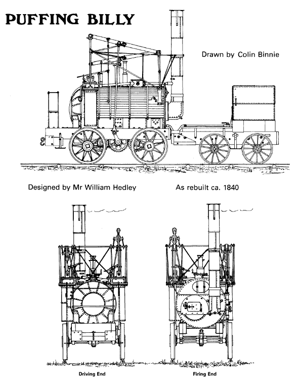
Here at last was the successful adhesion locomotive. In all three engines were built to this design and acquired the nicknames by which they are known today. i.e. Puffing Billy, Wylam Dilly and Lady Mary.
They were built as plateway engines, i.e. they had smooth flangeless wheels whilst the `rails` resembled pieces of angle iron arranged so that the flange bore against the inside of the wheels and kept things on the straight and narrow. No record appears to exist of the engines in this condition so we will rapidly pass on to the first rebuild.
Things are a little easier at this stage for we have no less than three different sketches of the engines in this condition by Messrs Wood, Partington and Chapman. Unfortunately, `different` in this case should be read as `differing` though each shows an eight wheeled engine with bogies or a compensated frame.
The whole of the motion and the beams were mounted farther forward and somewhat higher than in the condition illustrated in the present article. The drive to the wheels was even more indirect in those days with the crankshaft and its attached gear mounted above, and meshing with, and idler gear shaft in approximately the present crank position.
About 1830 or so the engines were again rebuilt, this time as four wheelers to run on edge rails utilising flanged wheels. Certainly they were illustrated as eight-wheelers in 1825 and were illustrated as four wheelers in 1844. This conversion conferred an odd distinction, justified mainly by a play on words, that the Billy family were the earliest engines to run on smooth rails.
Not the first engines to run on rails nor yet the earliest engines built (Puffing Billy was the thirteenth of the noble order of steam locomotives) but I don`t think that any earlier engine ever got round to running on edge rails.
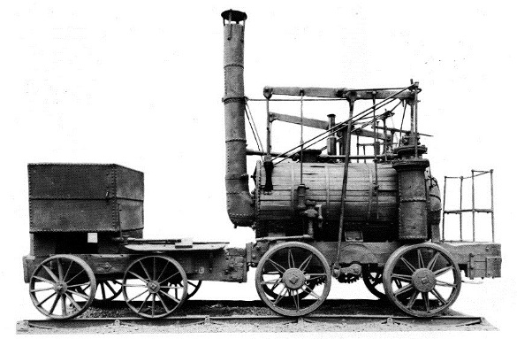
It is in this condition, i.e. that of the engines preserved in London and Edinburgh, that l would like to present `Puffing Billy` as a wonderful example of the heroic age of the blacksmith engine builders. The present locomotives are certainly not completely original, too much rebuilding has intervened but, like grandfather`s famous spade, the identity and the ideas are still there.
Let us take a really close look at `Billy` for there is a great deal more to it than a clumsy boiler on a crude frame with some strange links waving about like an upturned insect. Let us start with the frame and wheels.
The frame is indeed simple, consisting of a pair of solid baulks of oak bolted and stayed to equally solid cross members. To the bottom of the frame are bolted two pairs of plain trunnion blocks which take the axles. A pair of trunnion blocks form the crankshaft and two more pairs for the intermediate gear shafts. Billy, of course, antedated the coupling rod and relied on gears to couple the wheels together.
A quick look at sketch 1 will explain it better than my poor words. The axle and gear shafts are interesting since they reflect the problems facing the engineer of the day. Both driving wheels and the gear are fitted onto squared sections of the axle.
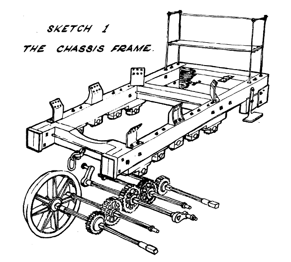
The actual bearings are, of course, round in section whilst the remaining sections are octagonal. This was not mere caprice on the part of the designer. It is extraordinarily difficult to produce a straight round shaft of any length by any of the normal methods of the blacksmith. The round sections were, therefore, kept no longer than needed for the bearings. The exceptions were the ends of the crankshaft.
The crank was fitted on to a circular shaft and secured by three tapered pins fitting into holes drilled down the joint between shaft and crank. The reason for this was presumably the difficulty in getting the two cranks properly quartered. It would have been quite a problem for a blacksmith to get two square sections accurately aligned at opposite ends of the same shaft.
The square seatings for the wheels and gears afforded a ready means of achieving a positive drive without recourse to the complications and need for accuracy of the modern press or shrink fit. A reasonably accurate square hole and matching shaft can be produced by hammer and file alone.
The aperture in the wheel was considerably larger than the end of the axle. By means of small iron wedges tapped into the gap the wheel could be induced to run reasonably concentrically and without serious wobble. Any discrepancies could easily be taken up by the `rust fit` a favourite and very effective ploy of the pumping engine builder.
To produce a rust fit the gaps in the joint were packed with a mixture of iron fillings, sal-ammoniac and urine. Within a week the packing was a solid mass of rust and the gear wheel very solidly fixed to the shaft, for rust is considerably greater in volume than the iron which produces it.
The driving wheels fitted at present are of the split spoke variety but are certainly not original; be that as it may they have been under Billy since at least the middle forties. I rather suspect that the original wheels were similar to the ones under the tender.
Please note the present oddity of Billy`s wheel whereby one set has eight spokes and the other ten. Split spoke wheels are favourites of mine and these really are beauties so let us have a closer look at them.
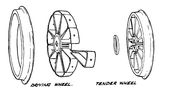
The basic construction of a split spoke wheel is shown in sketch 2. Pieces of wrought iron were bent into triangular shapes, assembled into an embryo wheel and the hub cast around the ends of the spokes. The tyre was then fitted and bolts or rivets inserted to make everything solid.
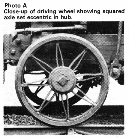
Billy, of course, is the odd one out. The ten spoke wheel is quite conventional with a bolt or rivet between each spoke`. The eight spoked one is slightly different in that it does not appear to have fitted the tyre too well and has therefore had small wedges driven in between the ends of the spokes to expand to fit the tyre.
A careful study of Photo A will also reveal that the hub of this wheel, at least, was not in the middle of the wheel. The wedges on one side of the axle have been driven farther home so that the rim runs true even if the hub is eccentric.
The tender wheels are even more interesting and posed a pretty problem to me when I first examined them. The material appeared to be cast iron yet the spokes were straight, although a conventional cast iron wheel of the period would have had curved spokes to allow for the differing cooling rate of hub and rim.
Not only are the spokes straight but there is virtually no draft or taper on the parts to enable the pattern to be withdrawn from the mould. But even this faded into insignificance when it was realised that the hub pattern could not have been withdrawn from the sand anyway for the centre section of the hub is smaller in diameter than either the front or back diameter. In fact there is a small recessed pocket in the hub between each pair of spokes.
To add to the confusion there is a small bead running down the joint between the spokes and the rim. That wheel is just the sort of wheel that would be produced today by fabrication from flat cut steel plate and section. That small bead in the corner looked suspiciously like an oxyacetylene weld. But oxyacetylene welding was a twentieth century technique not used for producing tender wheels in the middle of the nineteenth!
When you have that sort of problem the only thing to do is share it with someone of greater knowledge and I knew just the fellow. Brian Iremonger of the Science Museum staff came and crouched down in front of the mysterious wheels and we scratched our heads in unison. Many old books were consulted before we solved the mystery.
The wheel was cast. The reason that the straight spokes had not snapped was simple. The hub is split longitudinally into two halves each containing two sides of the square axle hole. The hub is held together by two wrought iron rings shrunk onto the ends of the hub so producing my `uncastable` pockets between the spokes.
What about the welding beads? Simple again, the pattern used for the wheels was crude and had no fillets or rounding off of the corners of the mould. The foundry man had therefore just taken a spoon and scraped away a little of the sand mould on each corner to enable the iron to flow easily and to avoid the concentrated stress at the sharp corner. So much for my mystery; a perfectly logical elegant solution to a manufacturing problem had come to light. It set me looking at Billy in a new light. These notes are the imperfect result.
Moving upwards on the engine to the gears coupling the wheels together, there is one little mystery I have not solved. To run smoothly together the gears should all have a common diametrical pitch, i.e. the ratio between the number of teeth and the diameter of the pitch circle should be constant. In lay language the gear teeth on a gear should be just as large on one gear as the next. Applying the usual formulae to `Billy` does not seem to work. The variation of diametrical pitch is too great to be just my error of measurement.
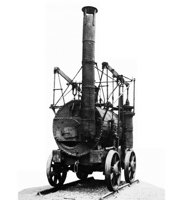
The boiler is interesting from several aspects. Firstly it has a return flue. This means that the firebox is at the chimney end. The flue in the form of a two foot diameter tube which passes forward through the boiler very nearly to the domed end before doing a `U` turn, reducing to one foot diameter and returning to the chimney. The grate is merely a set of firebars across the bottom third of the ingoing large flue.
Secondly, the cylinders which appear to be rather crude wrought iron affairs partially inset into the boiler are a great deal more sophisticated than that. The visible cylindrical portions are merely casings forming extensions of the main boiler shell. The cylinders proper are of cast iron and sit immersed in steam and hot water inside the casings.
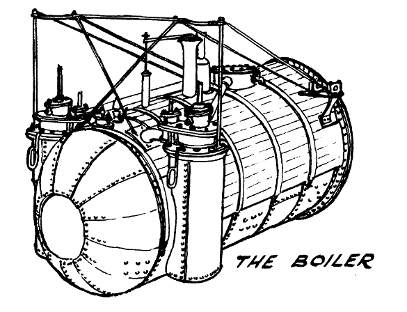
Thirdly the incredible number of plates used to construct the boiler, cylinder casings and chimney bear witness to the difficulty in obtaining large pieces of plate in the days before the rolling mill.
On top of the boiler is the basic framework for the motion and valve gear. A true set of motion brackets if ever I saw them. The important parts to notice are the bearings on the brackets at the flanged end and the raised horizontal rail passing transversely above the cylinders. The remaining struts on the boiler serve only to support this transverse rod. The rod itself is not straight but is bent into a horizontal omega loop directly above each of the cylinders.
In the parallel motion diagram this rod is labelled `fixed pivot 1` and the bearings mentioned above are labelled `fixed pivot 2`.
Brighter readers will have realised that we are now regarding the motion from the other direction!
The parallel motion depicted here was a very cunning substitute for crosshead and slide bars as a means for guiding the piston rod in a straight line. Consider the beam not in the position drawn but with the far end depressed so that the joint between the piston rod and the beam is in line with fixed pivot 1. In this position the beam is horizontal and fixed pivot 2 is vertically below the pivot between the beam and the `A` bracket.
A pair of links pivoting on fixed pivot 1 and on pivots located halfway along the beam restrain the beam in the horizontal direction. In particular note that the distance from the joint between piston rod and beam and the link pivots on the beam is the same as the length of the links.
When the piston rod moves the end of the beam up or down the links cause the centre of the beam to swing in an arc about fixed pivot 1. Now as long as the other end of the beam is constrained to move horizontally only, the piston rod end will move in a precisely similar arc about the joint between links and beam. The piston rod end therefore shares two similar but contradictory motions and moves in a straight line.
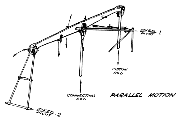
At least that is what should happen but the other end does not move in truly horizontally but in an arc about fixed pivot 2. This movement imparts an error in the form of a slightly S shaped motion to the piston rod end instead of the desired straight line.
The connecting rod takes the drive from a point partway along the beam down to the crank whilst from a point adjacent to the piston rod joint hangs the valve rod.
The valve gear is wonderfully simple, without any of that lap and lead nonsense to worry about. A long lever with a handle on the end is pivoted in a fork mounted on the cylinder head. The valve spindle is attached to this lever between the handle and the pivot.
The lever is extended beyond the pivot so that the end of the lever is pushed in one direction then in the other by the strikers on the valve rod as the valve rod rises and falls with the beam. A nice touch is the way that the end of the valve lever is split into two springs to take the shock when struck by the strikers.
To start the locomotive the driver would move the valves into the appropriate position by hand so as to produce motion in the required direction and open the regulator. As the locomotive started to move so the valve operation would be taken over by the strikers on the valve rod.

With this gear steam was admitted for almost the whole stroke of the piston. None of that expansive working or notching up nonsense here.
An interesting point is the provision of fork ends or strap ends to the motion rods and links. Once again this is an example of design within the technological abilities of the age.
On a rod with a fork or strap end the effective distance between the bearing centres can be simply varied. Filing the inner brass and tapping the cotter in a bit will shorten the centres or by putting a bit of packing under the inner brass will lengthen them. The rods are quite lovely examples of the blacksmith`s art, just look at that forked fork at the top of the valve operating rod.
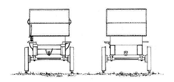
Another interesting example of blacksmith type fabrication is shown in tender diagram at the horn plates for the tender wheel bearings. Here we have a top plate with a half bearing integral with it. This is held in place by the side cheeks whose upper edge is drawn out to form fixing bolts. The bottom is closed by a square section keeper secured with a cotter. A nice touch is provided by the outward projection of the top plate beyond the face of the frame. This rubs against the back of the wheel hub and keeps the tender body centrally between the wheels.
One last point before drawing this short account to a close, the gauge of `Puffing Billy` is five feet. This provides a marvellous opportunity to build a true scale model to run on `O` gauge track to a scale of one quarter inch to the foot without using those nasty foreign millimetres.
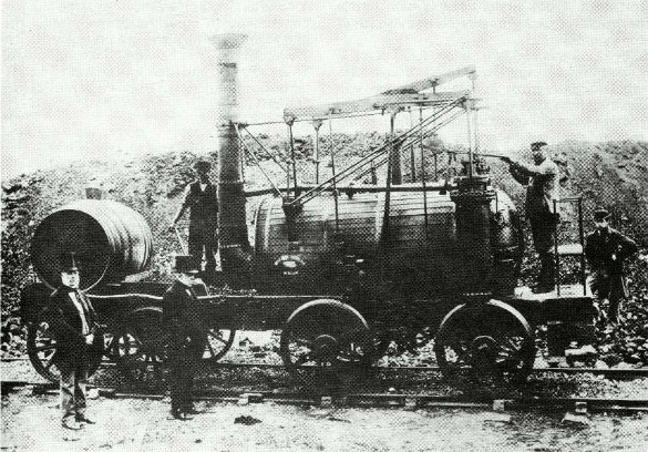
There are differences in detail between the two engines but one can see the general agreement between the machines. For the time the driver`sfacilities were excellent even a bench seat.