Plastic Moulding is generally considered rather an exotic means of producing components, requiring large quantities and expensive tools. I hope to show that this is not the case, but indeed that it is a method eminently suited to the enthusiastic amateur.
First a few words of explanation on the process itself, which is really very simple.
I realise that there is more to the subject than can easily be dealt with in these pages, but I would ask all the chemists and professional moulders amongst our readers to bear with me ; if only on the grounds that five minutes actual experiment will establish the conditions required for a successful moulding, when five hours` dissertation on the theory of plastic moulding will only confuse.
The rig itself may be considered as being similar to a hypodermic syringe, the granulated plastic being placed in the cylinder and heated until it is molten. The plastic is then injected into the mould cavity and solidifies there, forming the component required.
Our requirement for a hypodermic syringe must be re-stated in practical terms, in the form of an easily heated cylinder with piston to force out the plastic, and a nozzle to ensure it goes where it should, together with a handle to hold it by. My own unit consists of a turned brass cylinder of 7/16 in. bore and 3/16 in. wall thickness, silver soldered into a recess cut into the bit of a 60 w. SOLON soldering iron.
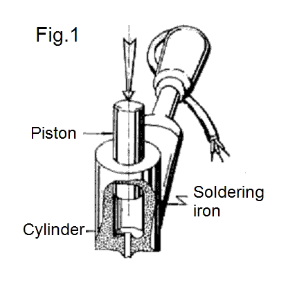
The iron should naturally be dismantled, since a red heat is required for silver soldering, and not many irons work as well as they should if heated this far.
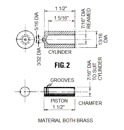
The cylinder is fitted with a suitable piston and the whole unit swathed in asbestos tape. A sketch of the unit without the tape forms Fig. I, and a drawing of cylinder and piston forms Fig. 2.
What good the grooves around the business end of the piston do I don`t really know, but they look very technical and are not doing any harm.
The chamfer around the upper end is to prevent the end bellying out like a decrepit cold chisel when it has been in use for some time.
The rest of the moulding rig consists of a suitable mould and a means of applying the necessary pressure to the piston. Now, I propose to leave the subject of moulds and mould making to a later article, and ask you to consider the mould at this stage as being a metal block in the top of which is a countersunk hole- the in-gate.
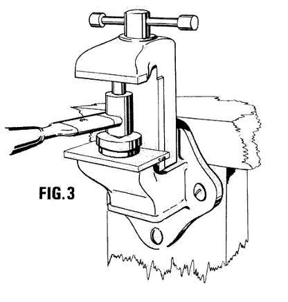
The means of applying. pressure is very simple; all that is required is a large vice mounted so that the screw works vertically with the handle at the top. Fig. 3 shows what I mean and saves me a whole paragraph of description; it also shows how the rig is put to use, so I think that I had better explain that next.
The whole operation forms a simple cycle which, once the rhythm is acquired, becomes very easy, and quite respectable production rates may be achieved.
A Simple Cycle
The cycle is as follows: the piston is removed from the cylinder and the cylinder filled with plastic and tamped down inside with an odd bit of metal, as if filling a pipe. The unit is switched on and, after a while, the unmistakable but not unpleasant smell of hot plastic will be noticed; a little longer, and molten plastic will start to exude from the nozzle. The nozzle is then wiped clear of plastic and placed in the in- gate of the mould and, immediately it is in place, the piston is pressed home.
The unit is removed from the mould, the piston removed and the cylinder refilled with plastic. The mould is opened and the component removed whilst the fresh plastic is brought up to moulding temperature in the cylinder. The mould is reassembled and the cycle repeated.
Having said all that I must admit that I do not do things in an upturned vice myself, since I have a small arbour press which is rather more rapid in action. The principle is the same however in both cases and the vice is perfectly adequate.
Temperature
One other requirement is for some means of regulating the temperature.
The simplest solution that I know to this problem is a Simmerstat from an old electric cooker. This device is in effect a means of switching an element, or anything else for that matter, on and off at short intervals. As the knob is turned toward the hotter
end of the scale the element, or what have you, is switched on for a longer period and off for a shorter period. In the with it
jargon of today, the mark-space ratio is varied.
This is taking us rather a long way away from our injection moulding, so suffice it to say that such a control fitted to the bench so as to regulate the output of the mains socket is very useful for other things besides controlling moulding units; soldering irons for instance.
However, back to the problems of moulding. I have indicated the need to control the moulding temperature without really stating why, so I must repair the omission. When a plastic is heated, it melts, and the more it is heated the more runny
it becomes until a point is reached at which it starts to decompose and gives off a most unpleasant smell.
When a plastic has been heated to this degree it is quite useless to try to mould it, as the properties for which it has been selected just do not materialise. If the plastic is not heated enough, it will not run into the mould properly and will fail to fill it. Failure to fill the mould could be the fault of the mould design as well, but I will deal with that later.
What should happen is this: when the piston descends, it should do so easily and smoothly and come to rest with a small jerk when the mould is full. If the temperature setting and the rhythm of the worker are well matched, then this will happen time. after time, and you will wonder why I made it sound so difficult. Sometimes, however, the piston comes to a soggy
halt, and the ‘mould will fail to fill; assuming all is well with the mould the heat should; be turned up and a slower and more deliberate rhythm`. adopted.
Of course, the piston sometimes fails to stop at all and molten plastic squirts, from every joint of the mould. This is fortunately rare and the cure simple: turn down the heat and,or adopt a faster rhythm. This same cure works wonders with components exhibiting heavy flash. The object of the exercise is to get the plastic just hot enough to fill the mould completely, and no more.
I have said nothing yet about the plastics them selves, but I will give some notes on them and their characteristics after I have dealt with the moulds.
Moulds
This month I would like to deal with the construction of some suitable moulds for use with the moulding rig described last month. The essential features of three types of mould are shown in Fig. 4 and the first feature common to all three types is the cavity in the middle. This cavity has the same shapes as the part required but in reverse.
The one essential thing about the cavity is that the component must come out when the mould is opened.
So you think that is obvious ?
It is, but I have made several moulds that had a decided affection for the components made in them, and were very loath to let them go.

The Ingate
The sides of the mould must taper toward the parting line as shown in the diagrams, and this feature, termed draft
is the most awkward design limitation on moulded components, though a little forethought in choosing the parting line can minimise the effect.
The other feature common to all is an ingate
orhole-for-squirting- plastic-in-by.
In Fig. 4(a) the ingate is fairly large and injects directly into the component through the top plate. This means that there is a large lump of unwanted plastic sticking out of the side of the finished component. It will be appreciated that the component must also be more difficult to extract from the mould, though a small punch placed in the ingate and tapped gently will do wonders.
In Fig. 4(b) the ingate is on the parting line and may be reduced to a small diameter for a small distance at the lower end to reduce the size of the moulding marl: on the component. It is important that the length of this reduced bore is kept small since injection is usually into a cold mould, and considerable cooling of the plastic may take place before the material ever reaches the cavity. Opening the mould results in immediate release of the component, but the force required to keep the mould closed whilst moulding is higher than in 4(a).
Fig. 4(c) is an indirectly injected version of Fig. 4(a) which also incorporates the small final diameter of 4(b). It does have, however, one other merit in that when the first wave of incoming plastic is cooled by the walls of the ingate, the resultant slug of cooler plastic is injected into the cold Well
and the mould filled from the hotter plastic in its wake.
There are many other types of mould but all are derivatives or cross breeds of these three, so I will waste no further time on generalities but get down to the description of an actual mould.
First mouldings
Now the first thing for which I ever made a mould was anS
gauge spoked wagon wheel; that was about 1960 and, believe me, it left a lot to be desired.
However, no other insulatedS
gauge wheels were available at the time and those early wheels served their purpose until the present series replaced them.
Note the very fine scale spokes

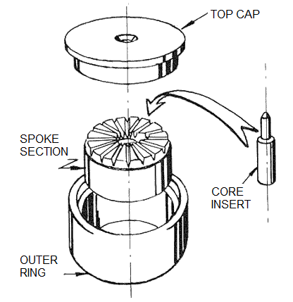
Wheel Mould
I think that a description of a wheel mould will serve as well as any for a starting point. The components for this mould are shown in Fig.5, and the first component to be discussed will be the outer ring. The outer ring (Ref. A) is faced off square at both ends and bored through, the diameter of the bore being the same as the inside diameter of the front face of the tyre i.e. that funny little step that occurs between the wheel proper and the tyre. The reverse contour of the tread is then turned in the end of the bore so producing a cavity for the wheel rim.
The use of interchangeable outer ring sections allows the production of alternative profiles at will. The spoke section (Ref. B) is turned to fit closely into the ring and machined so that the top face is recessed into the assembled mould by the same amount as the spokes are recessed below the rim in the back of the wheel. It will be noted that a generous taper of about 20 degrees is allowed on both the recess for the boss and the shoulder which forms the portion of the wheel visible inside the tyre.
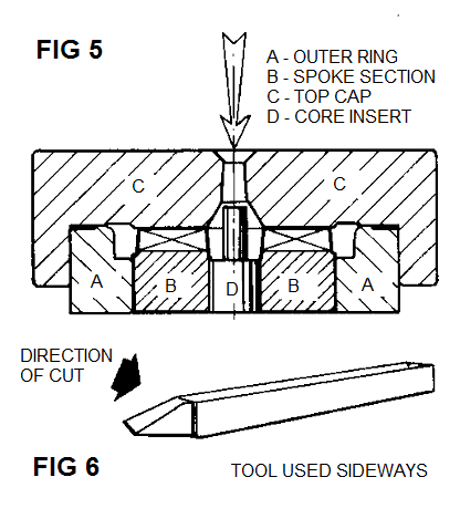
All the above operations can be done without removing the job from the chuck, so ensuring concentricity even with the sloppiest lathe. With the work still mounted in the chuck, a tool shaped as shown in Fig. 6 is mounted on its side in the toolpost, so that when the cross-slide is operated it cuts a groove across the face of the stationary workpiece. If the tool is fed in to cut only 0,005 in. or so at a time, no difficulty will be experienced in cutting the cavities for the spokes. After cutting the cavity for one spoke the work is indexed round to the next position, and the next spoke cavity cut.
It will be appreciated that the cavities for the spokes must be made radial and that, to ensure this, the tool must be accurately set to centre height.
This is best done by unscrewing the chuck with the job still in the jaws and putting a lathe centre in the headstock; the tool may then be set at centre height with the aid of a magnifying glass and sheet of white paper held behind the lathe, to provide an evenly illuminated uncluttered background.
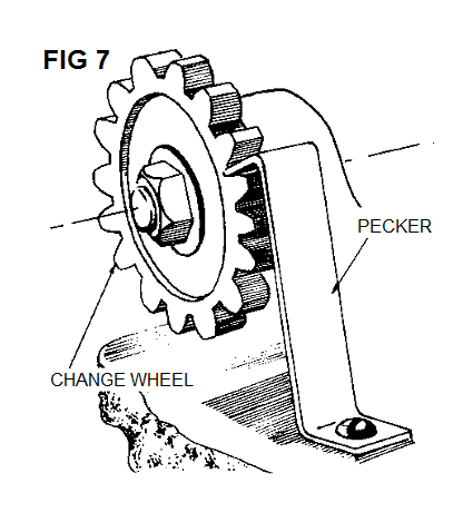
If the lathe used has a suitable indexing mechanism, then all is plain sailing, but should one not be fitted it is usually a fairly simple job to arrange a mounting for a change wheel or other suitable gear at the other end of the headstock spindle. (See Fig. 7,)
A piece of strip metal with the end bent at right angles can then be used as a `pecker` in the teeth of the gear wheel, and will be found quite rigid enough for the modest loading experienced in this type of work.
The top Cap (Ref. c) is next: this is a straight forward turning job. It is essential that when the top cap is assembled to the other parts and stood on a flat surface, close fits are achieved both between the boss of the top cap and the face of the spoke section and also between the shoulder of the top Cap and the outer ring.
The only remaining part is the core insert which determines the axle diameter.Only one feature here is of special interest; if the end of the insert is flat and is made so that it leaves only a small clearance between the end of the insert and the inside of the boss cavity, then a piece of rod may be inserted in the wheel and the sprue snapped off without further ado.
Some experiment is necessary to determine the actual clearance here but is not difficult nor protracted. In use, the mould is merely assembled and stood on a flat steel plate under the moulding rig, After moulding is complete the mould is pulled apart and the wheel knocked out.
Now, if the area of the wheel as seen from the back is less than the end area of the piston, then the pressure of the end of the moulding rig upon it will keep the mould closed without the need for clamp screws. In practice, spoked wheels inS
gauge and below can be made in this Way, but forO
gauge or larger gauges and for disc wheels in smaller gauges it is necessary to screw the mould together A simple way is to pass two screws down through the top cap and outer ring and into the underlying metal plate.
It will be appreciated that by replacing the appropriate section other related types of wheel may be produced. Outer rings producing fine or coarse scale flanges have been mentioned, but the spoke section may be readily replaced to produce disc, three-hole or split-spoke wheels, and the core insert may be changed to vary the axle hole diameter. This should suffice for this month; next month We shall discuss driving wheels and plate moulds.
Driving Wheels
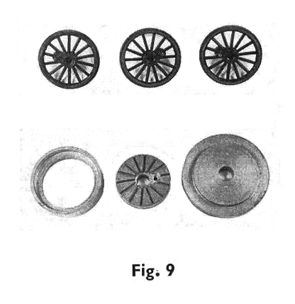
Driving wheels are simple items, the mould for one being shown in Fig. 9. A small amount of milling is necessary here to produce the cavity for the boss; this is done in my case with a home made cutter, which has tapered sides to produce a cavity having the required draft.
The set up for milling the boss cavity is simple. The spoke section of the mould is first made as if it were an over-spoked wagon wheel, and removed from the chuck. It is then clamped to the vertical slide (if available) or to the cross-slide if not, and carefully centred.
This is best done by putting a drill, of the same diameter as the bore, shank outwards in the chuck and feeding the job towards it.
If the job is correctly centred the shank of the drill will just enter the hole without jarring. The drill can then be replaced by a small centre drill, the work traversed by an amount equal to the crank throw, and a hole drilled in the crank pin centre. This should be opened out to 3/64 in. diameter and drilled right through.
Without changing the lathe setting, the special cutter is substituted for the drill, and fed in until the spoke cavities are just cleared. It is then slotted through into the bore. This completes the lathe work, and the boss cavity must then be finished to final profile by careful work with a scraper.
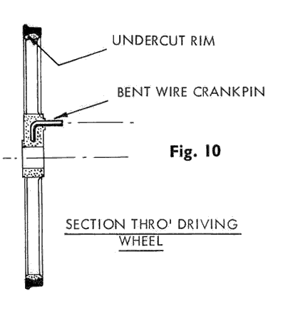
Metal Rims
Driving wheels must have metal rims, and these are easily turned with the aid of a form tool and must be provided with an undercut inside the rim. See Fig. 10. It is essential that the rim is the same thickness as the depth of the rim cavity in the outer ring. Its outside diameter must also be accurate to ensure concentricity between mould and rim.
The crank pin is simply produced by bending a piece of 18 s.w.g. brass wire as shown and inserting the long end in the hole in the mould. The rims are now dropped into the mould, and the plastic injected. The resultant wheels are concentric, have very firmly fixed insulated crank pins and the rims are also really solidly fixed.
Plate Moulds
To represent the plate mould family I have chosen a very simple mould indeed. In fact, this mould was made in a great rush to satisfy my young son. He had visited the M.R.C. Exhibition and had twisted Dad`s arm until Dad had bought one of those delightful Baldwin 4mm. narrow gauge engines for him. Once home, he wanted to build trucks, and made vast numbers of Plasticard boxes which he declared only needed wheels and under frames to be narrow gauge wagons.
I made one metal underframe set in about 25 minutes, in which time he had made two more little boxes. A mould seemed the only escape, so one was produced in a rush. It was started at about ten-thirty and had produced three dozen side frames by lunch time.
Moulding is far quicker than scratch building each one, and the parts are all the same!

Fig 11 shows the mould, which is laminated from flat plates, hence the term `plate mould. When a mould of this type is made, the first thing to do is to drill the dowel holes and fit the roughly shaped plates together. The outer faces of the mould can then be finished. The cavity is marked out on the centre portion of the mould, and the axle centres or other reference points
So far, we have the moulding rig itself and the production of some simple moulds. All of these have been in metal and fabricated in one way or another. It is possible, however, to cast moulds in either metal or epoxy resin.
The bare bones of the process. are as follows: an original pattern is made and mounted on a back plate, if flat, or embedded in modelling clay up to the line, if not. The whole thing is then coated with a parting agent (a quick squirt with the wife`s, aerosol polish) and a casting taken from it. This is trimmed up and fitted with a metal top plate in the case of the flat pattern and the necessary in-gate, etc., drilled. In the case of the awkwardly shaped pattern a second casting of the other side must be taken to form a complete mould.
I have been deliberately sketchy in the details of mould production in this manner since I have failed to achieve the same quality and precision in moulding from the cast mould as from the metal mould. Whilst in other hands the process is demonstrably feasible there is a lack of crispness about the mouldings which I have made so far. Hence, since this is supposed to be an explanation of the things I can do, and not, as with some writers, an admirable and lucid explanation of something that I can’t, I will abandon this facet of plastic moulding to an abler pen.
Back on firmer ground again, I think the only further information required before every modeller becomes his own plastic moulder, is some information on plastic materials.
Thermoplastic materials
Material: Acrylic
Injection Temp`: 210-240 C
Melt Viscosity: High
Solvent: Chloroform
High viscosity, requires high pressure. The melt is rubbery in texture. Available in colours and clear
Material: Acetal
Injection Temp`: 190-240 C
Melt Viscosity: Medium to High
Solvent:
Good for gears, bearings but not recommended for the modeller
Material: Acrylonitrile Butadiene Styrene
Injection Temp`: 220-250 C
Melt Viscosity: High
Solvent: M.E.K. Chloroform
Wide range of grades from tough and rubbery to rigid. Good impact resistance
Material: Cellulose Acetate Butyrate
Injection Temp`: 180-220 C
Melt Viscosity: Medium
Solvent: M.E.K. Chloroform
Wide range of grades as above. Colours and clear
Material: Nylon, Polyamide
Injection Temp`: 225-280 C
Melt Viscosity: Very Low
Solvent:
Has sharp melting point. Low viscosity means close fitting moulds.
Material: Polyvinyl Chloride
Injection Temp`: 220-260 C
Melt Viscosity: Medium
Solvent: M.E.K. not good
Wide range of grades. Not much use to the modeller
Material: Polystyrene
Injection Temp`: 160-260 C
Melt Viscosity: Medium
Solvent: M.E.K.
Good general purpose plastic. Many solvents. Easily available
Material: Polythene Polyethylene
Injection Temp`: 220-260 C
Melt Viscosity: High
Solvent:
Not much use to the modeller. Cheap. Does not take paint well. Has considerable shrinkage.
Material: Polypropylene
Injection Temp`: 220-260 C
Melt Viscosity: High
Solvent:
Flex cracking almost unknown. Similar to Polyethylene
Material: Polycarbonate
Injection Temp`: 270-320 C
Melt Viscosity: High
Solvent:
Not easy for the amateur to use. Really tough thermoplastic
A Frames for a Monorail
Having been foolish enough to start doing my own plastic moulding and even more foolish to explain in print how it was done (see Model Railway News, 1968), I found myself inundated with suggestions about which component l should produce next. Alas, few of the enthusiastic enquiries were anything to do with the method of manufacture but were of the Why don`t you produce some left handed duckets for an E.M. gauge Chinese junk? I could use at least two myself
variety.
Just as I was beginning to go sour on the whole business, Adrian Garner and Don Boreham came to my rescue. Do you think it is possible to mould these
they cried, pulling out a drawing. Of course! Of course! Nothing easier,
I twittered in my innocent enthusiasm. I drew diagrams, explained everything, my head swole mightily under their flattery and when they left, bearing with them full details of how the mould was to be made.
I realised that I, not they, was committed to produce mouldings for Listowel and Ballybunion ‘A’ frames to a scale of 16 mm/1 ft. Was ever man so betrayed ?
But betrayed or not, l still had the mould to make. Fig. 1 shows the actual ‘A’ frame and fig. 2 the slightly simplified version produced. It will be noted that the angle forming the cross bar has been merged into the ‘A’ itself, while the clamps for the rails have been thickened and simplified.
The mould into which the molten plastic was to be squirted was built up from several metal plates, layered together like a sliced loaf. In each of the pieces are pierced apertures corresponding to the various sections of the frame. There are three layers for the frame itself, plus two cover plates.

The centre plate into which is cut the common flange of the frame is -018 in. thick and the outer two are -O64 in., i.e., the width of the flange less the thickness of the centre plate. Into these are cut the projecting flanges of the frame. Fig. 3 should make this clear.
Examining the plates in order we have: Plate 1 which is the cover plate with the in-gate or ‘hole for putting in the plastic‘ in the top. Plate 2 is split into two and has filed into the joint edge the cavity for the flange of the crossbar with the ‘chairs’ for the rail at the ends. Two pieces of rail are secured half in—half out of the plate to provide the slot for the rail in the ‘chairs’.
There is also a long slot which provides distribution between the in-gate in plate 1 and the four inlets in plate 3. Plate 3 provides the main flange of the frame and has a loose centre section (plate 3 1/2). Plate 4 provides the other flange of the side frames and has both a loose section (plate 4 1/2) and an inset piece of rail for the top chair.
Plate 5 is the other cover plate. No screws or dowels have been shown in the drawing but in fact there are four 1/4 inch diameter pins through the corners of the plates and two 3/32 inch diameter pins passing through plates 1, 2, 3 1/2, 4 1/2, and 5. All these loose parts, pins, etc. tend to make moulding and extraction slow but Don, using my press and equipment made about four hundred frames in a week. The mould itself accounted for about nine hours work and Don put in about forty hours! So, all told, we managed to produce ‘A’ frames for less than one minutes work apiece.